Before the pump is assembled, all parts should be inspected. The mating surface of the parts, especially the friction surface of the mechanical seal should be cleaned. The sealing surface should not have obvious scratches, cracks, bumps and other defects. If any of the above defects should be replaced.
assembly:
Press the water retaining ring onto the motor shaft and fasten the middle seat to the motor with bolts.
After applying a lubricant such as petroleum jelly to the rubber ring of the mechanical seal static ring, press the static ring assembly into the middle seat, apply the cleaning grease on the sealing surface, install other sealing parts, install the flat key, the impeller and Stop the washer and press it with the bolt.
Note: The sealing rubber ring of the mechanical seal static ring is easy to be sideways during installation, which will cause the machine seal to leak and should be carefully inspected during installation.
Apply a proper amount of grease to the sealing end face of the middle seat and install an O-ring. When installing the O-ring, the sealing ring is easy to fall off and fold. Please be careful not to cause the water leakage to lift the motor assembly. The impeller is placed down into the pump body, then tightened with bolts, and the pipe plugs and venting plugs are installed. .
Turn the rotor by hand to check for any stuck.
Disassembly:
Follow the reverse steps of installation.
Note: When disassembling the mechanical seal, you can not directly hit the static ring with a hammer or a hammer, use the wood to gently tap and slowly remove the static ring. If it is difficult to disassemble due to dirt accumulation, it should be cleaned and disassembled first.
Installation, operation and maintenance of the unit:
installation:
When installing, choose a place close to the conveying liquid, so that the pump is installed in the suction line with small suction height and short ziu. Note: The distance between the unit and the surrounding obstacles should be greater than 150mm, so that the motor fan Have access to adequate air sources.
When the pump is used in a place where the vibration requirements are strict, the damper (pad) can be used and must be installed according to the manufacturer's instructions.
The installation of the pipe should be securely fixed, and the pipe support at the pump flange should be sufficiently rigid to allow the pump to withstand the weight of the pipe.
The pump set should be installed to avoid direct sunlight and rain.
A vacuum pressure gauge shall be installed at the inlet of the pump, and a pressure gauge shall be installed at the outlet flange to observe and control the operation of the pump. The range of the pressure gauge should be 2~3 times of the actual pressure.
Pump inlet and outlet lines should be fitted with gate valves for easy maintenance and operational adjustment.
Wiring: It must be correctly wired according to the nameplate. When wiring, the terminal must be firm and not allowed to loosen. Otherwise, it will cause poor contact and lead to phase loss. In order to ensure reliable operation of the motor, an overload protection device should be installed at the electrical switch, and the set value of the protection device should be adjusted according to the current requirement on the motor nameplate.
Warning: If the overload protection device is not installed, the motor will burn out due to overload due to the full opening of the outlet valve and the sudden increase of the current when the flow is too large or under certain circumstances.
In the suction state (water level is lower than the impeller axis or the water level is lower than the pump suction axis), the standard installation pressure of the pump is H-=10-(NPSH)r-0.5-hw, hw is the resistance loss of the suction line ( The unit of calculation in the formula: m).
If pumping water from the pool, the length of the straight pipe before the suction port of the pump should not be less than 3 times the diameter of the inlet, and the depth of the suction nozzle below the water surface should be greater than 1.5 times the diameter of the inlet and not less than 500 mm. The distance between the suction nozzle and the pool wall should be greater than 1.5 times, the bottom of the pool should be more than 1.5 times and not less than 500mm, and a filter should be added. The total area of ​​the filter should not be less than 2~3 times the area of ​​the suction nozzle. .
Note: The installation of the horizontal section of the suction pipe should be inclined downwards in the direction of the water flow to prevent the air from being trapped.
In order to facilitate the filling of the pump into the pump before starting, a bypass valve can be added at both ends of the check valve to open the bypass valve to fill the pump before the pump starts, and then close after filling, which is convenient for use. For pumps used for high-rise buildings with water supply or outlet pressure greater than 0.2 MPa, in addition to the gate valve at the discharge port, a check valve should be installed between the pump outlet and the gate valve to avoid sudden power failure and high pressure water return to cause impeller damage.
run:
Open the inlet valve and bleed plug, close the outlet gate valve, and close the bleed plug after filling the pump with water.
Before starting, use a screwdriver to turn the fan motor fan blades to check the flexible operation of the motor.
Jog the motor to determine if the direction of rotation of the pump shaft matches the direction of the rotary marking on the pump (clockwise rotation from the motor end).
Warning: It is strictly forbidden to test run when there is no water in the pump to avoid damage to the mechanical seal.
When the inlet gate valve is fully open and the spit gate valve is closed, start the water pump, open the pressure gauge, and gradually open the outlet gate valve until the required operating condition (the running time should not exceed 3 minutes when the outlet gate valve is closed), pay attention to the current when the motor is running. Do not exceed the rated current.
Note: The operating point flow rate is not greater than the large flow rate given in the performance table. When running, the actual head H=(P out-P in)/0.0098 should not be less than the large flow point given in the performance table. The corresponding head is suitable (P is the value of the pressure gauge at the outlet, P is the value of the vacuum gauge at the inlet flange of the pump, pressure unit: MPa, head unit: m). The ideal and efficient operating conditions are the intermediate points given in the performance table. The outlet gate valve control can be adjusted by observing the inlet and outlet (vacuum) pressure gauges.
In the case that the characteristic curve of the device (pipeline) has been determined, if the operating condition of the pump is to be adjusted, the preferred method is to change the speed or adjust the diameter of the impeller. For the implementation plan, please consult the manufacturer.
Shutdown sequence: Close the gate valve on the discharge line----motor---pressure gauge.
maintain:
Always check whether the operation is smooth, the wear and leakage of the mechanical seal, and replace the seals in time to prevent the pressurized water from entering the motor.
Frequently check the temperature change of the motor casing, the pump is running normally, the temperature rise of the motor is allowed to reach 80 °C, if necessary, further check whether the motor current is overloaded and the three-phase current is unbalanced.
Always check the inlet tank for any changes in floats and water levels. If the inlet tank falls below the low water level of the zui, the pump should stop running to avoid cavitation and damage the impeller. If necessary, the gate valve can be adjusted to reduce the water output of the pump and promote the water level of the pool.
Pay attention to the changes in pressure gauges and ammeters, find abnormalities, and take appropriate measures in time.
When the pump is out of service for a long time, it should be drained to remove rust and coated with anti-rust grease.
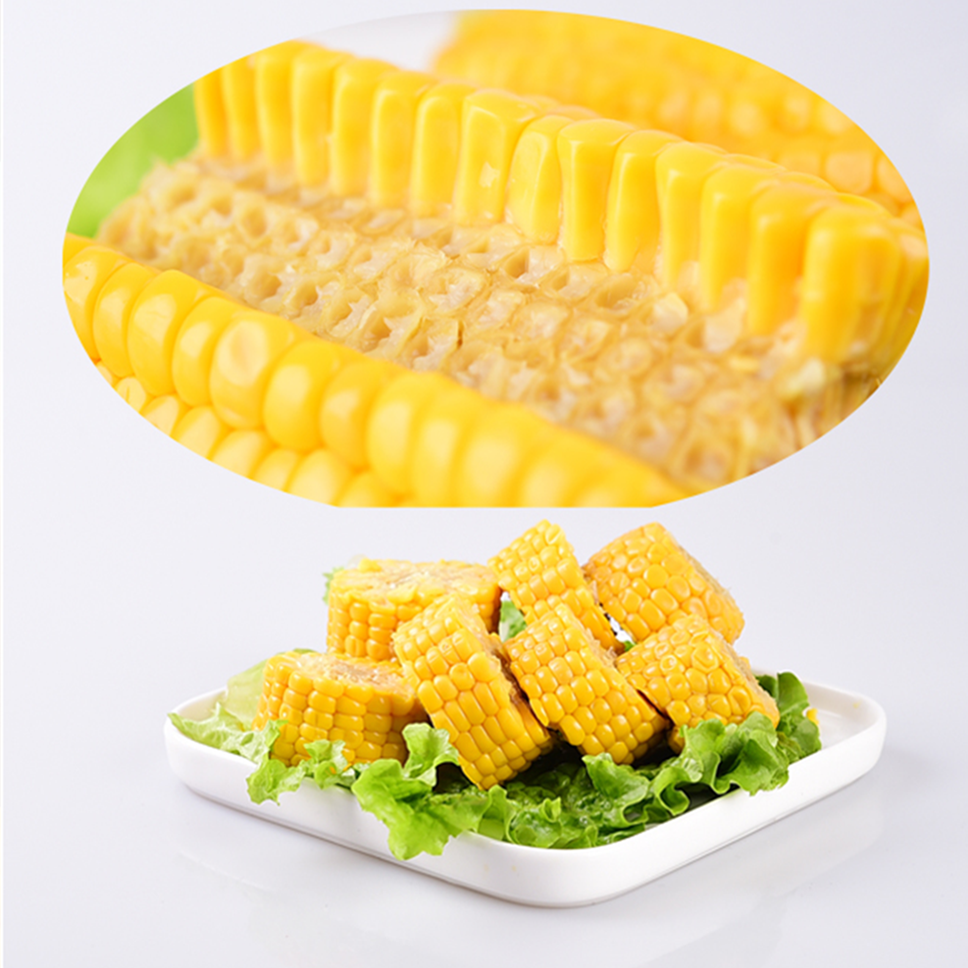
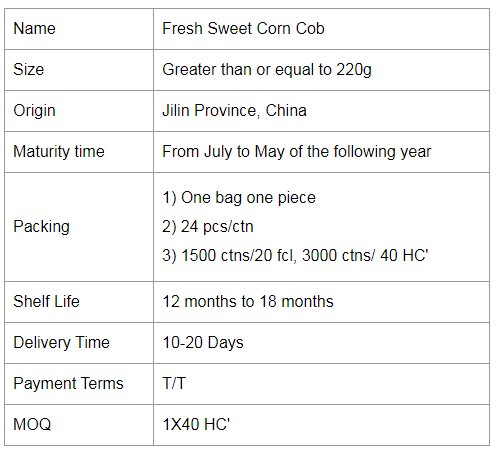
Sweet corn. The light green outer leaves of sweet corn are yellow grains, but also purple and yellow. The grains are small and round, the skin is thin and soft, tender, sweet and delicious.Contains carotene, zeaxanthin, with the effect of eye protection.
Sweet corn is most often boiled into soups. It is a favorite soup for children and adults, whether it is made into a clear corn soup with ribs or pureed with cream.
Corn is also a good choice for consumption during weight loss because of its high available energy. The metabolic energy of corn is 14.06 MJ/kg, with the highest being 15.06 MJ/kg, the highest of the cereal feeds. This is mainly due to the fact that there is very little crude fibre in corn, only 2%, while the nitrogen-free leachate is up to 72% and the digestibility is up to 90%; on the one hand, corn has a high crude fat content, between 3.5% and 4.5%.
So how do you cook a sweet corn?
1. Leave the leaves
If you strip the leaves off, the corn will lose nutrients and flavor when it cooks, so it's best to leave two thin leaves to make it easier to cook and have a nice aroma.
2. Soak
Soak the corn in cold water for 20 to 30 minutes before boiling, then boil it on high heat to give it a bit more chew.
3. Add salt
When the water is boiling, add a little salt to amplify the sweetness of the corn.


Corn Cob,Fresh Corn Cob,Ready Sweet Corn,Single Packed Sweet Corn Cob
Jilin Province Argricultural Sister in Law Food Co., Ltd. , https://www.nscorn.com